
Overview
Developed an autonomous line-following robot from scratch: SolidWorks CAD with FEA validation, custom PCB with 6x TCRT5000 IR sensors on STM32F401RE, and a C/C++ PID controller with trapezoidal integration, anti-windup, and low-pass filtering. Innovated by repositioning the battery pack between gearboxes to lower CG, adding upper strut-braces for torsion resistance, and using an arc-shaped sensor PCB for earlier curve detection. Added Bluetooth-triggered 180° turnaround via HM-10 BLE.
Key Highlights
Gallery
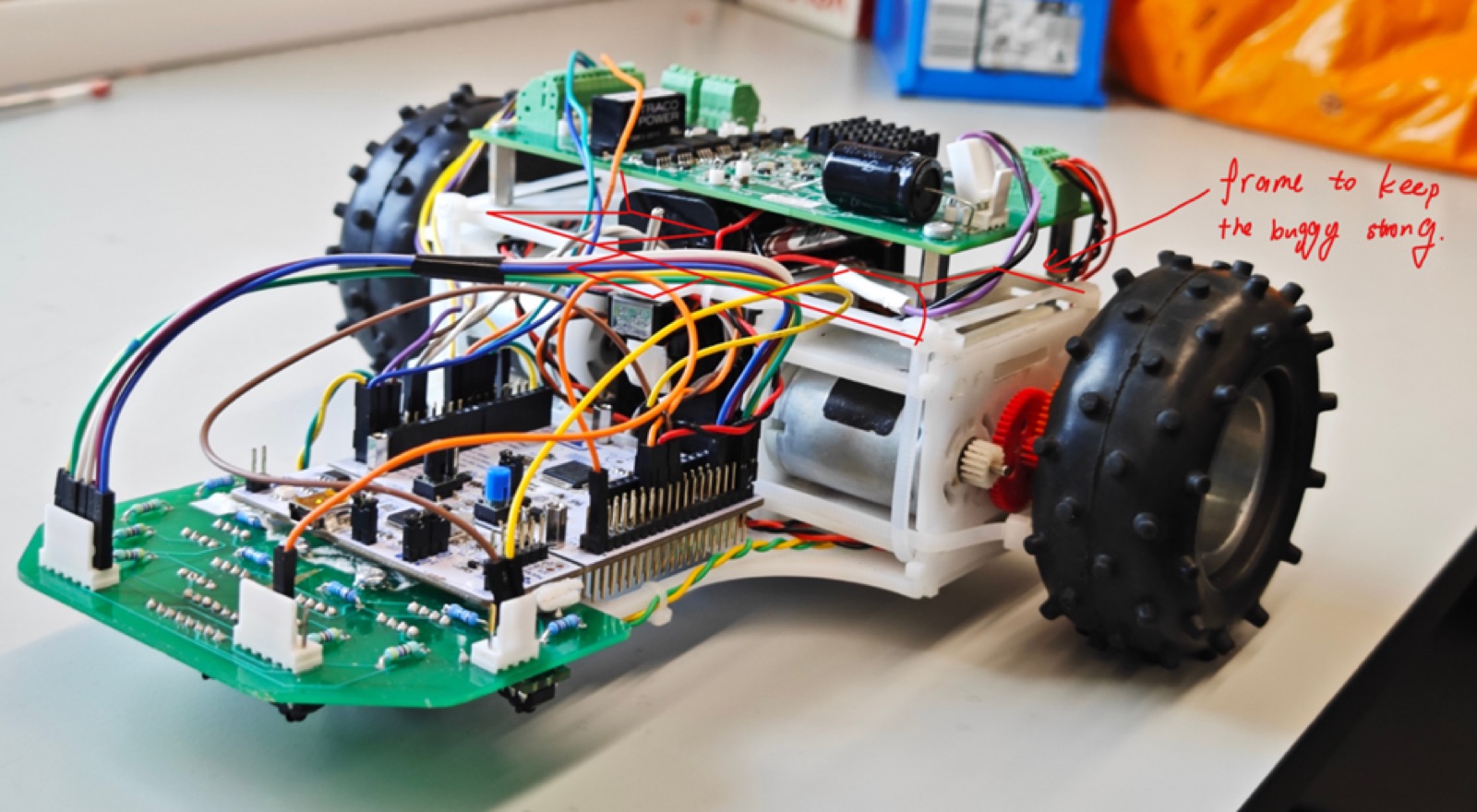
The completed buggy — battery pack repositioned between gearboxes for lower centre of gravity
Deep Dive
My Contributions
As part of Group 39 (5-person team), I led the mechanical design effort: initial concept drawings, original FEA structural analysis, full chassis redesign for lower CG, mechanical design details including standoff stacking and weight-reduction cutouts, all physical wiring (sensor board, motor controller, power, BLE module), and PID coding assistance for optimum tracking.
Chassis Design Philosophy
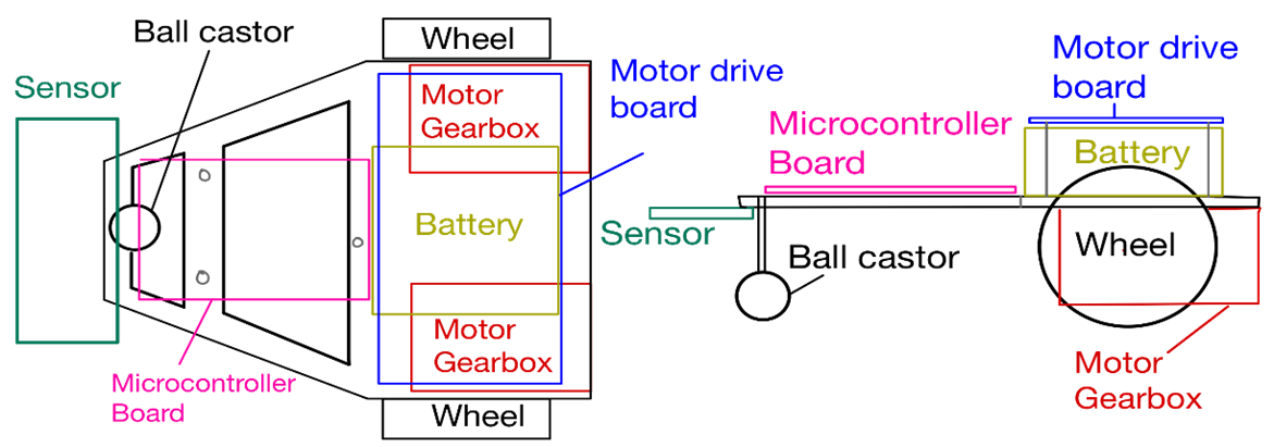
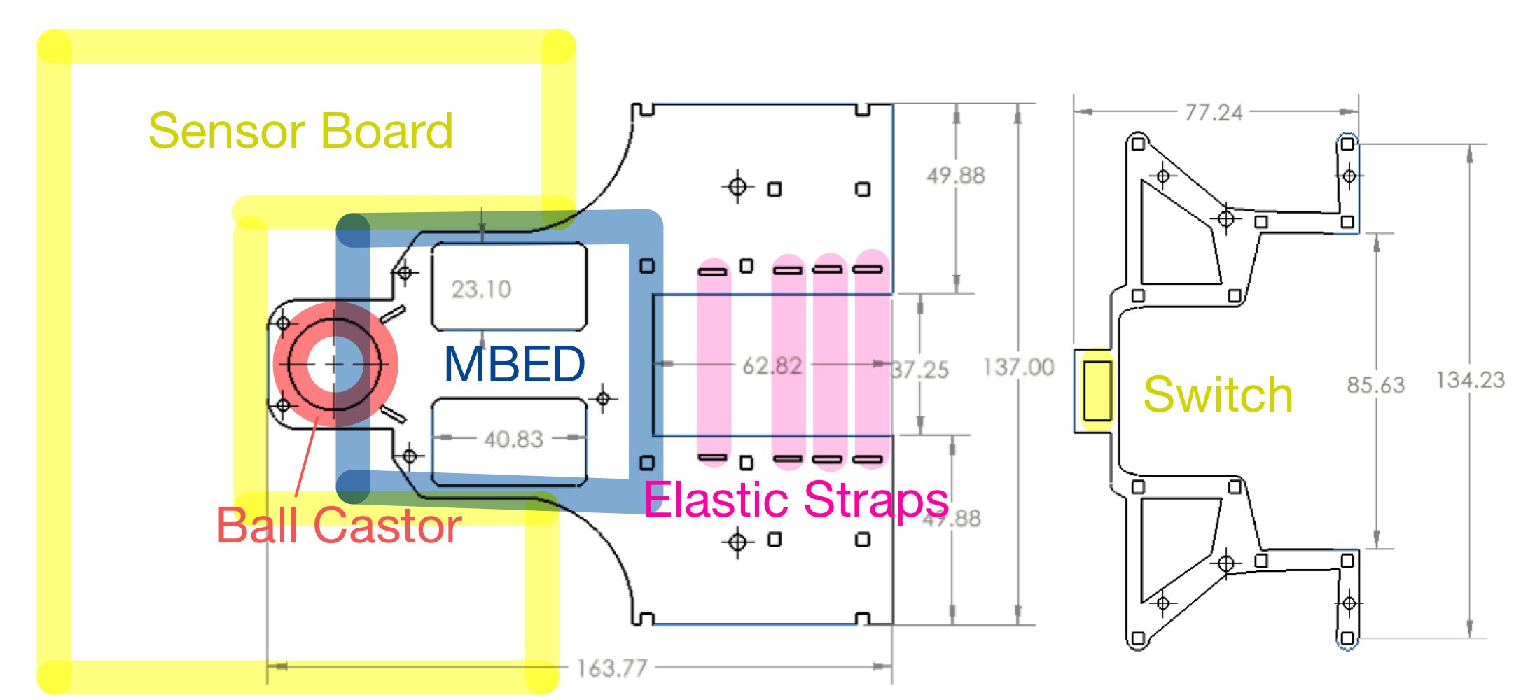
I redesigned the chassis around three principles: low centre of gravity, compact form factor, and sensor proximity to ground. The battery pack was repositioned between the gearboxes, lowering the CG closer to the drive shaft for better weight distribution during directional changes. Varying-length standoffs compactly stack the sensor board, mbed, chassis base, and support frame while keeping sensors adjustable. A sandwich assembly replaced long screws, saving approximately 80g. An upper cross-member links motor protrusions for torsional rigidity while doubling as the motor-controller and power-switch mount.
Structural Analysis
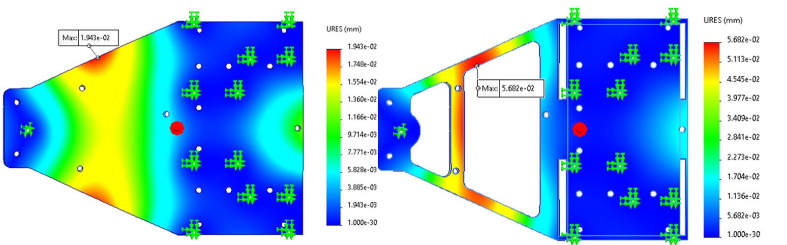
FEA simulation on the original chassis design revealed flex points under load. The redesigned chassis with upper strut-braces and repositioned weight distribution eliminated these failure modes. The 3D-printed chassis uses an arc-shaped sensor PCB mount at the front for earlier curve detection — sensors detect the line further ahead, giving the PID controller more time to react.
Wiring Architecture
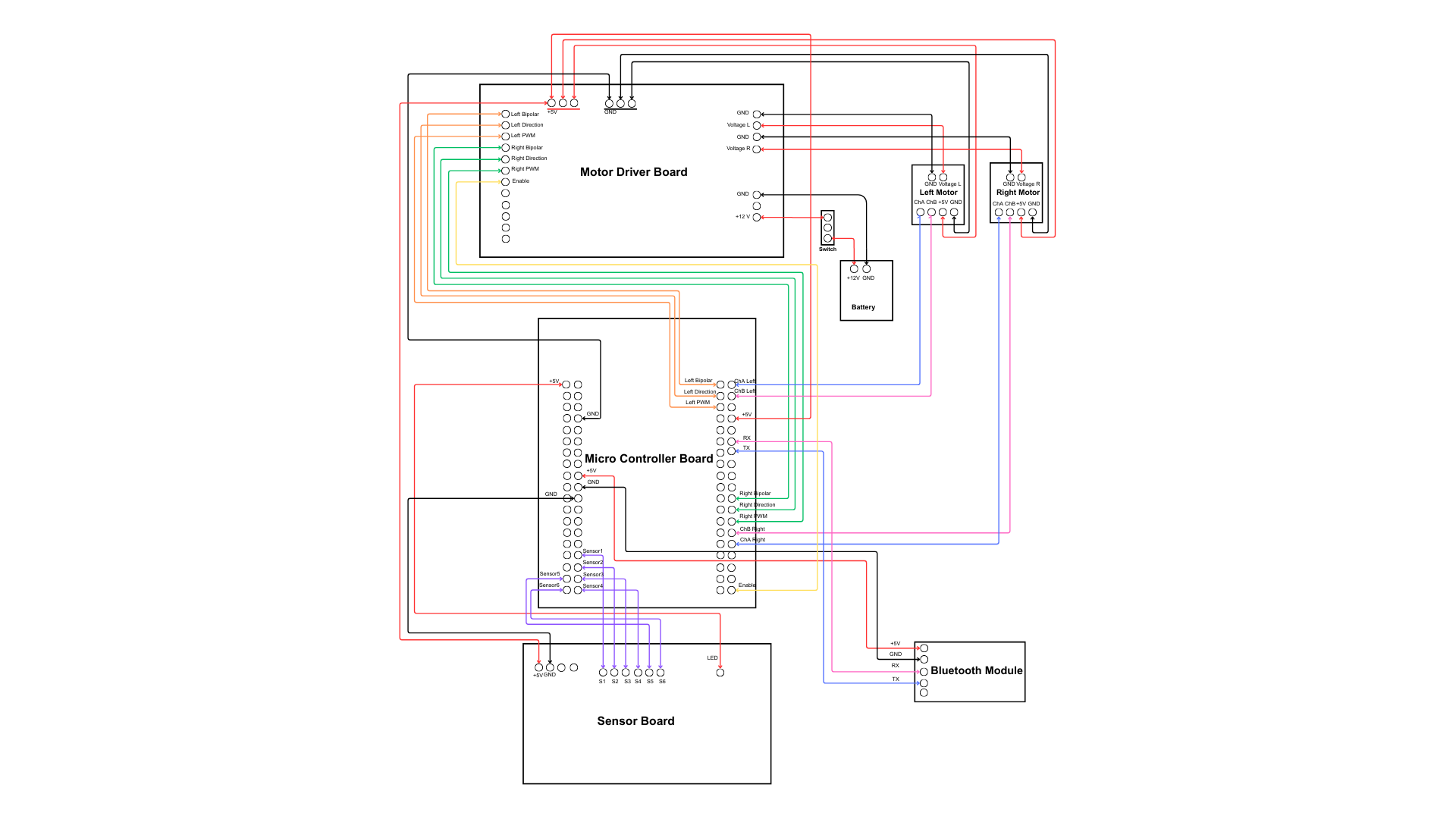
I developed the complete wiring diagram and executed all physical wiring. Sensor to mbed: 6 analogue wires from TCRT5000 sensors plus IR LED control via ULN2003 Darlington array. Mbed to motor driver: PWM direction and enable signals to dual H-bridge. Power: battery through switch to motor controller plus 5V regulator to mbed and sensor board, with clean power separation to avoid noise on analogue lines. Bluetooth: UART TX/RX from mbed to HM-10 BLE module for wireless 180° turnaround trigger.
PID Control System
The controller uses trapezoidal integration for the integral term (more accurate than rectangular), anti-windup clamping to prevent integral saturation during sharp turns, and a low-pass filter on the derivative term to reject sensor noise. The 6-sensor IR array with background subtraction provides a weighted position estimate that feeds into the PID loop. Tuning was done empirically on the physical track.
Interactive Lab
PID Tuner — Make the buggy follow the line!
Adjust Kp (proportional), Ki (integral), and Kd (derivative) gains. High Kp = aggressive turns but oscillation. Kd = damping. Ki = steady-state correction. Complete 2 laps to get your score.